The XViCO X3 (sometimes also known as the Pioneer?) has appeared on eBay in the US for fairly inexpensive prices.
I found a couple of reviews online. I always find Angus Deveson's reviews on Makers Muse to be helpful, and
this review was no exception. However, it was light on some of the nuts-and-bolts specifics I wanted to know. Now that I've bought one, I'll try to fill in the gaps.
XViCO Website and Contact
I believe
this is the XViCO website, though it doesn't seem to have anything on the Pioneer as of 2019-02-22.
The site lists
yfm@xvico3d.com as a contact address, but this doesn't work:
The response from the remote server was:
550 Mailbox not found. http://service.exmail.qq.com/cgi-bin/help?subtype=1&&id=20022&&no=1000728
Not an auspicious beginning.
Power Supply Unit (PSU)

The power supply seems to be a universal-input type, so no need to switch it between 240/50Hz or 120/60Hz lines. Its output is rated 12V @ 20A, and dimensions are 200mm x 60mm x 40mm. The big electrolytics are made by a small-volume manufacturer (Dongbaohe), and I don't think I've seen the brand around, so it is probably a very low-cost unit.
The wire gauge seems to be generous, though. And the fact that it took solder means it's at least partly made of copper.
One bad thing you will want to rectify: while the PSU side of the
heavy-gauge output wires have had spade lugs nicely crimped on, the
other end has simply been stripped and tinned. The problem is that this
solder will eventually soften with heat and mechanical stress, making
the connection to the board intermittent. This risks fire. It would have
been much better to crimp ferrules in place instead of tinning the
wire.
 |
| Soldered Ends = Bad |
|
 |
| Crimped Ferrules = Better |
Board
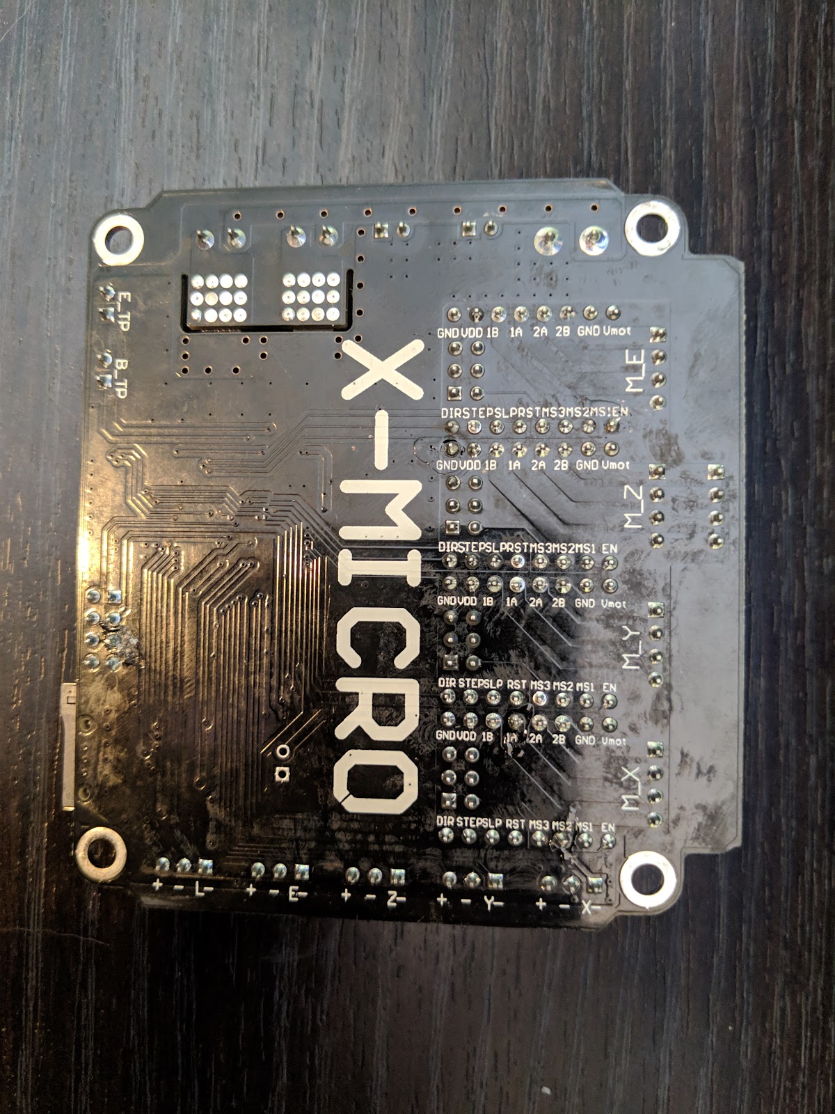
The main board is based on an STM32F103 processor, so this isn't yet another ATMega unit. The stepper drivers seem to be RAMPS compatible, though I have not verified this. I have not yet found a source for the firmware, and it certainly does not come on the included generic SD Card.
The back of the board gives the pinouts for the various headers and endstops.
The slot around the hotend and bed heater MOSFETs is curious. Maybe to keep heat from soaking into the rest of the board?
I have not yet found the manufacturer for certain. It may be made by
Two Trees in Shenzhen, who also sell them on Aliexpress.
The drivers are marked HR4988SQ.
Delrin Wheels
Unlike the Creality printers, the rollers on this printer do
not seem to be adjustable for tension. They certainly do not have the nice eccentric adjustments that Creality's printers have. This is my biggest disappointment, though I've been mostly impressed that the tension seems to be reasonably good.
Build Plate
The other exciting development for me was the removable glass build plate. It seems well-executed, though unlike Angus' review unit, mine is not textured.
The plate has holes for hex-head M3 x 30mm bolts, but XVico used Philips screws here, so they tend to spin in the plate when trying to make Y adjustments. A drop of superglue will probably be enough to hold these in place, but it's still an annoying oversight.
The glass dimensions are 220mm x 220mm x 3mm. While there's room at the back for electrical connections on a heated plate, the plate is going to be right against the ABS plastic of the frame, which doesn't seem like a great idea to me. In any case, the generic 3mm heat beds I have are 215mm x 215mm x 3mm, so they won't fit without modification. I do wish Angus would have shown the heated bed that XVico sent, though I understand why he didn't install it.
Hot End
Mine's even worse than Angus'. It has a single fan, with part of its output "diverted" to make a part cooling fan. The "duct" is 3D printed, and has already partly melted from proximity to the hotend.

The X carriage has four M3 bolt holes spaced 14mm apart for mounting the hotend. The hotend is bolted to the middle two holes.
There is a ~52mm PTFE-ish tube between the bowden coupler and the brass nozzle. The coupler is for 4mm OD tubing, threaded 1/8" NPT. It's branded "DONT".
The nozzle and heatbrake seem to be M7.
The heater cartridge seems to be 6mm x 20mm, retained with a setscrew. Not sure how the thermistor is retained.
X Axis Tensioner
The X axis tensioner has a small problem. The hex nut rubs against the bearing, creating a lot of friction and making the tensioner wheel hard to turn.
 |
| The hex nut rubs on the outer bearing race. |
I solved this by using one of the spare M5 bolts that came with the printer, and an M5 nylock I had on hand. The bolt head is small enough in diameter that it won't rub on the bearing outer race.
A nylock nut on the back allows for very tiny increments of torque to hold the pulley in place:
I'll add more as I investigate further.


